русский
 Español
 عربى
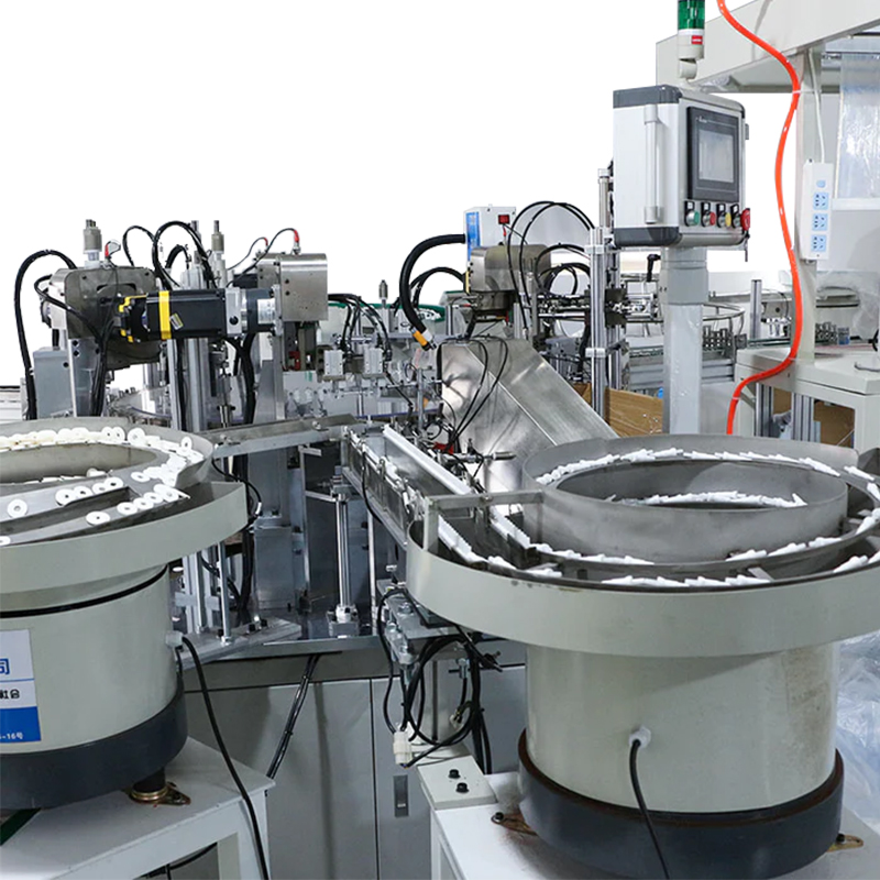
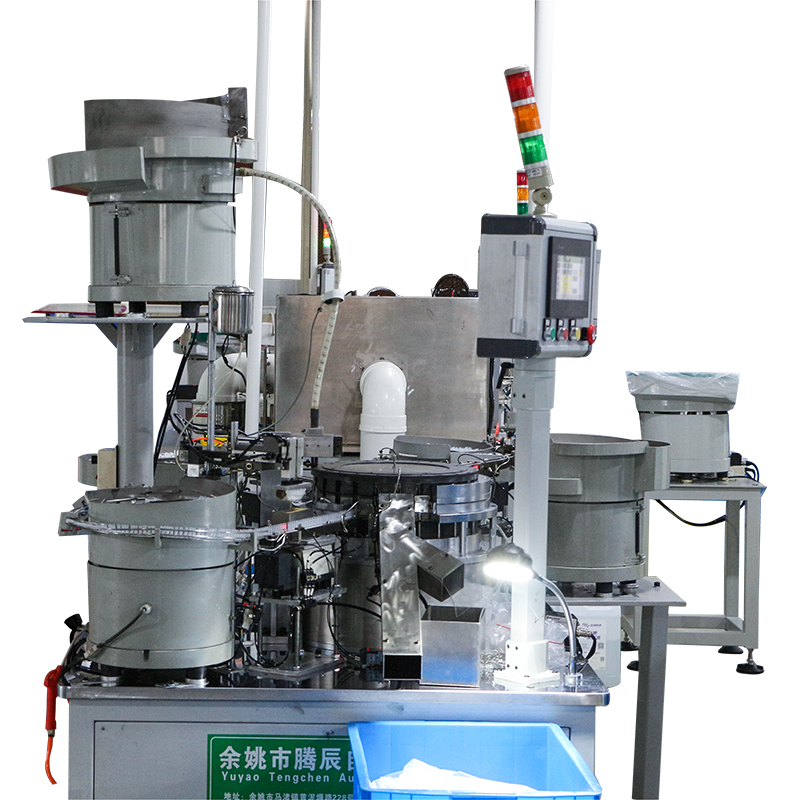
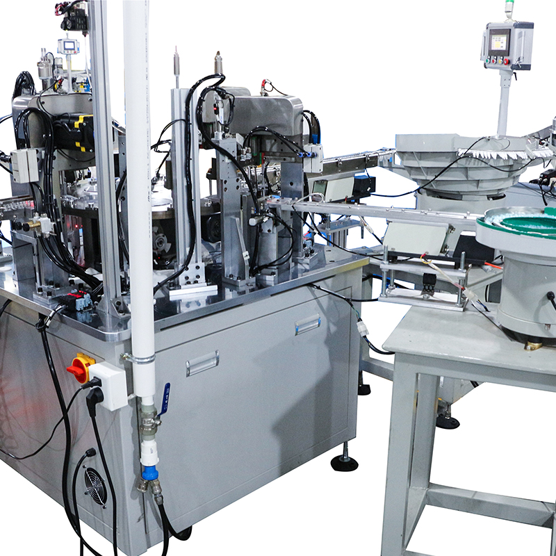
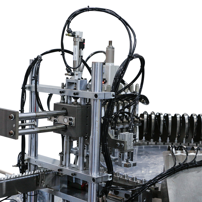
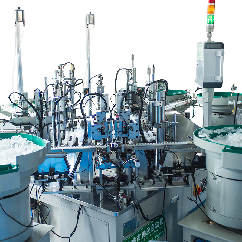
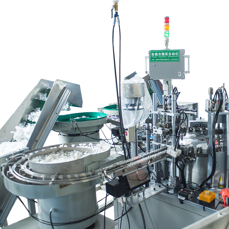
The typical Cap Assembly Machine operates on a three-phase 380V–480V AC power supply at 50/60 Hz, with full-load energy consumption ranging from 3 kW to 15 kW depending on machine size, automation level, and output speed. Entry-level machines handling 50–100 caps per minute may draw as little as 3–5 kW, while high-speed fully automated systems producing 300–600 caps per minute can consume 10–15 kW under sustained full production load. Understanding these requirements upfront is critical for facility planning, electrical infrastructure sizing, and long-term operational cost management.
Standard Power Supply Requirements for Cap Assembly Machines
Most industrial Cap Assembly Machines are designed around globally common electrical standards to allow deployment across different regions and facilities. The following specifications represent the most widely observed configurations:
| Parameter | Standard Specification | Notes |
|---|---|---|
| Voltage | 380V / 480V AC (3-phase) | Single-phase 220V available for compact models |
| Frequency | 50 Hz / 60 Hz | Dual-frequency models available |
| Rated Power (small) | 3 – 5 kW | 50–100 caps/min output range |
| Rated Power (medium) | 5 – 9 kW | 100–250 caps/min output range |
| Rated Power (high-speed) | 10 – 15 kW | 300–600+ caps/min, servo-driven systems |
| Compressed Air | 0.4 – 0.8 MPa | Required for pneumatic clamping and ejection |
It is important to note that in addition to electrical power, most Cap Assembly Machines rely on a compressed air supply for pneumatic actuators responsible for cap orientation, pressing, and rejection functions. Failing to provision adequate air pressure — typically 0.4 to 0.8 MPa at a flow rate of 200–500 NL/min — will directly degrade machine performance even if the electrical supply is correctly configured.
Energy Consumption Profile Under Full Production Load
The energy consumption profile of a Cap Assembly Machine is not static. It varies significantly across different operational phases and is influenced by several mechanical and electrical subsystems. Understanding the load curve helps facility engineers size circuit breakers, UPS systems, and power distribution units accurately.
Startup Inrush Current
During initial startup, a Cap Assembly Machine can draw 3 to 7 times its rated running current for a brief period of 0.5–2 seconds. For a machine rated at 7 kW, this translates to a peak inrush demand of 21–49 kW-equivalent current surge. This is why dedicated circuit breakers with delayed-trip characteristics (Type D or equivalent) are recommended rather than standard Type B breakers.
Steady-State Running Load
Under continuous full production load, the Cap Assembly Machine settles into a predictable consumption band. The primary energy consumers within the machine include:
- Servo motors and drives — typically accounting for 40–55% of total machine power draw, responsible for indexing, pressing, and torque application
- Vibratory bowl feeder — consuming 0.3–1.2 kW depending on cap weight and feed rate
- PLC and HMI control panel — typically 0.2–0.5 kW for the control electronics
- Vision inspection system — 0.1–0.4 kW for camera lighting and image processing hardware
- Conveyor and transfer systems — 0.3–1.0 kW depending on line length
- Pneumatic solenoid valves and actuators — indirect electrical load from solenoid coils, typically 0.1–0.3 kW
Idle and Standby Consumption
When a Cap Assembly Machine is powered on but not actively cycling — for example, during a brief line stoppage — energy consumption typically drops to 15–30% of full-load power. Servo drives in standby mode and the always-on control panel represent the primary baseline loads. Modern machines equipped with energy-saving modes can reduce idle consumption further by automatically powering down bowl feeders and non-critical actuators after a configurable timeout period.
Factors That Significantly Affect Energy Consumption
Not all Cap Assembly Machines of the same rated output will consume identical amounts of energy. Several application-specific and design-related factors influence real-world power draw:
- Cap material and weight: Heavier aluminum caps or multi-component caps with liner insertion require greater pressing force and more servo torque, directly increasing energy per cycle.
- Production speed: Running a Cap Assembly Machine at 90% of its rated maximum speed can increase energy consumption by 20–35% compared to running at 60% speed, due to higher acceleration and deceleration demands on servo systems.
- Drive technology: Older machines using AC induction motors with mechanical cams consume measurably more energy than modern servo-driven equivalents. Servo systems with regenerative braking can recover 10–20% of kinetic energy during deceleration phases.
- Ambient temperature: Operating a Cap Assembly Machine in environments above 35°C may require additional cooling for the control cabinet, adding 0.3–0.8 kW of supplemental HVAC load.
- Integration complexity: Machines integrated into fully automated lines with upstream filling machines and downstream labeling systems may carry additional shared conveyor loads billed to the Cap Assembly Machine's electrical circuit.
Practical Electrical Infrastructure Recommendations
When preparing your facility to receive a Cap Assembly Machine, the following infrastructure guidelines help prevent costly installation delays and operational faults:
- Dedicated circuit breaker: Always install a dedicated circuit breaker sized at 125–150% of the machine's full-load amperage to accommodate inrush current without nuisance tripping.
- Cable sizing: Use copper conductors sized per local electrical code with at least a 20% safety margin above rated current. For a 10 kW machine at 380V three-phase, this typically means 4 mm² conductors minimum.
- Earthing and grounding: Cap Assembly Machines with vision systems and servo drives are sensitive to ground noise. A dedicated equipment ground separate from building structural ground is strongly recommended.
- Power quality: Ensure total harmonic distortion (THD) at the supply point is below 5%. Variable frequency drives and servo amplifiers in the Cap Assembly Machine can both generate and be sensitive to harmonic distortion.
- Compressed air isolation: Install a lockout-capable isolation valve on the compressed air supply line to the Cap Assembly Machine for safe maintenance procedures.
Estimating Annual Energy Cost for a Cap Assembly Machine
To assess the total cost of ownership, it is useful to model the annual electricity cost of operating a Cap Assembly Machine across a typical production schedule. The following example uses a medium-class machine consuming 7 kW at full load, operating two 8-hour shifts per day, 250 days per year, at an industrial electricity rate of €0.12/kWh:
- Annual operating hours: 2 shifts × 8 hours × 250 days = 4,000 hours/year
- Total energy consumed: 7 kW × 4,000 hours = 28,000 kWh/year
- Estimated annual electricity cost: 28,000 × €0.12 = €3,360/year
This figure represents a modest and predictable operational overhead. However, for high-speed Cap Assembly Machines running three shifts at 15 kW, annual energy costs can reach €6,480–€8,100/year under similar rate assumptions. Investing in a servo-driven model with regenerative energy recovery can reduce this figure by up to 18%, offering a compelling return within 2–3 years of operation.
Questions to Ask Your Cap Assembly Machine Supplier
Before finalizing a purchase, users should request the following energy-related documentation from the Cap Assembly Machine manufacturer to ensure complete transparency:
- Full electrical specification sheet including rated kW, voltage, phase, frequency, and FLA (full load amperage)
- Inrush current value and recommended circuit breaker type and rating
- Compressed air consumption in NL/min and required supply pressure range
- Whether servo drives include regenerative braking modules
- CE declaration of conformity confirming compliance with the Machinery Directive and EMC Directive
- Energy consumption data at 60%, 80%, and 100% of rated production speed
A reputable Cap Assembly Machine manufacturer should be able to provide all of the above as part of the standard technical documentation package. Any supplier unable to supply verified energy consumption data at rated load should be approached with caution, as this information is fundamental to responsible facility planning and lifecycle cost analysis.